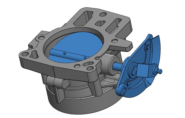
Using 3D CAD Models in the Design Process.
We’re excited to have guest author Scott Shuppert provide his insight into the importance of using 3D CAD models in the design process. Scott is a 30-year veteran of the scanning industry and the owner of CAD/CAM Services, a full service CAD conversion company.
By Scott Shuppert
As manufacturing has become more globalized, companies are being challenged to respond to the rapidly changing needs of consumers faster, better, and cheaper. Shortened product life cycles and the increased need for new models, customization, advanced technologies add to the demands of cost-stressed manufacturing firms.
Companies that evolve to respond effectively to these consumer demands have been proven to be more innovative, more successful and more profitable than those who don’t.
One way in which manufacturers keep one step ahead of the competition is by concurrent engineering. Concurrent engineering is a process that enables engineering and manufacturing to occur nearly simultaneously from shared 3D CAD data. For instance, 3D CAD models can be used as virtual prototypes, eliminating the time-consuming requirements for multiple physical prototypes until the engineering is “right”.
About 3D Models
There are three types of 3D models that can be mentioned in conjunction with design processes and concurrent engineering:
1. 3D wireframe, while not often used today, is worth mentioning simply because the approach to 3D wireframe is similar to that used in 2D CAD systems. Persons familiar with 2D CAD will understand these concepts: (1) each line has to be manually inserted into the drawing; (2) the final product has no mass properties associated with it; (3) the final product cannot have features added directly to it. The wireframe model is used to make the final engineering drawing views.
2. 3D “dumb” solids, also not often used today, are created in a ways similar to manipulations of real world objects. Basic three-dimensional geometric forms, such as prisms, cylinders, spheres, etc. have solid volumes added or subtracted from them, as if assembling or cutting real-world objects. These models allow for easy two-dimensional projected views to be generated. Basic 3D solids don’t usually include tools to easily allow motion of components, set limits to their motion, or identify interference between components.
3. 3D parametric solid modeling requires the operator to use what is referred to as “design intent”. Design intent simply means that the purpose of the design is taken into account when creating the model. How the design will be used dictates the relationship between features in parts and parts assemblies. If a feature is intended to be located from the center of the part, the CAD technician needs to locate it from the center of the model, just as it will be in real life. This is very different from “dumb” models, where the feature could be located from some more convenient area in the 3D drawing, so it would “look” correct, but, not in fact, represent the real world.
Parametric solids require the operator to consider the consequences of his actions carefully, because the objects and features created are adjustable. And just as in real life, moving a feature even a fraction of an inch may adversely affect other features, depending on how the original part was designed.
Parametric 3D solid modeling provides a virtual image of the design that can be rotated, manipulated, retrieved and modified at any time.
Nine Benefits This Up to Date Approach Brings
For many manufacturing companies, the combination of 3D modeling and CAD outsourcing brings a cost-effective approach to their processes. By outsourcing the 3D CAD modeling, manufacturers get accurate 3D models, while keeping their focus on manufacturing rather than modeling.
Outsourcing 3D CAD modeling services offer many advantages, including less infrastructure, greater competitive edge, less cost, the leverage of expert help, reliability and security. That is why 3D CAD model outsourcing is becoming increasingly common among forward-thinking manufacturers today.
The benefits of using a 3D CAD modeling service include: (1) Higher quality finished product; (2) Lower unit cost; (3) Identification and elimination of inefficiencies; (4) Increased workload capacity; (5) Better control of production; (6) Improved communication and collaboration; (7) Increased manufacturing accuracy; (8) More design flexibility; (9) Better design integrity
QC Engineering has extensive experience scanning and modeling parts. Your project will be personalized – managed by a highly skilled individual with whom you will have a direct line of communication. Contact us today.


